I recently bought an FM transmitter for my phone to broadcast to my car stereo. The transmitter market is the same as any other market — you get what you pay for. But because I’m not an audiophile, and the FM radio link only gives so much fidelity, I thought a cheap little thing would do the trick. Not to mention to go from the entry level ($6 shipped) to the big-boy level ($50 shipped), it is hard not to give the little crapper a shot.
I bought an SD/MMC/USB/MP3 Wireless in car FM transmitter (In Black) from Amazon. I guess $6 doesn’t buy you any sort of brand name whatsoever. It was the cheapest one I could find and appeared to have everything I needed — 3.5mm audio in, and USB port for (what I thought was) charging the phone. Once I received the device, it was about what I expected. Cheap plastic housing that was missing screws, but manged to get audio from my phone to my car stereo. Success!
….Except that it didn’t charge my phone. Instead, display of the transmitter would go blank upon plugging in the phone and there was no charging. Thinking I must have missed something, I checked out the product page and noticed that my assumption that the USB port was for charging was incorrect. It was for playing music off a USB stick! Oops. My immediate thought was:
“C’mon, guys! Why not just finish the design?”
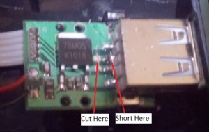
They were already 90% of the way there! The voltage regulator, the USB connector, the 12V car power source. Just let devices charge! So I thought I’d finish the design for them. Given my experience designing for mobile devices, I know that most mobile phones simply need the two USB data lines shorted in order to accept a charge (Otherwise the phone will attempt to enumerate and listen when told not to take a charge). This is what most cheap car and wall chargers do.
With only one screw holding the whole thing together, I opened it up to check it out. I learned two things right away:
- The designers used a 3805 fixed voltage regulator to knock down the 12V to 5V.
- Shorting the data traces was cake.
 In a quick bench test, It worked! But it immediately became clear as to why the designers did not allow charging with their FM transmitter: Heat Dissipation. In my head I could hear the designers offering a quick answer to my question in a very sarcastic voice:
“The design was for the cheapest possible FM transmitter for bottom-of-the-barrel consumers to buy. Heat costs money to dissipate, so NO CHARGING! Done.”
Touché. But since I was already in there, I thought I’d just add a little heat sinking. After all, the D²PAK package has a 3°C/W junction-to-case thermal resistance. Since the power burned by a voltage regulator is the current times the voltage that the regulator has to drop, I need to dissipate 7W of heat [(12V in) – (5V out) = (7Vdrop), with a 1A charge current for my phone, therefore 7V * 1A = 7W]. If I can get all that heat out, the junction will only rise 21º above ambient, which is more than acceptable. If it were only that easy.
D²PAKs don’t have a screw hole to attach a large heat sink, like a Gammell Crowbar. And even if there was a screw hole the extra slug of metal would need to fit in the housing. So I worked solutions with what I had:
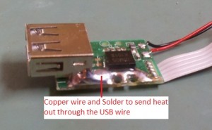
- Scrape off the soldermask on the copper pour to allow better heat transfer to the air.
- Solder a copper wire from the thermal pad to the USB connector housing
- Drill some holes in the housing to allow natural convection.
 Done. Except a temperature measurement found the part case getting up to 120°C, and that was with the board in open air. Bad news, since it is a good idea to keep the junction temperature down to 100°C, and I can calculate that it will be at least 141°C. But what to do? I’ve already picked the low hanging fruit, so the clever thing now would be to expand my junk bin and plunk down the $50 for a product designed to do what I want, right?
Right! ….It’s just that the cheap one is already on my desk. And all opened up. And its got my attention. I’ll try one more thing. I’m out of space near the hot part, but there is extra space elsewhere in the housing. Why not split up the power dissipation into another part? I can use 2 voltage regulators in series to share the power being consumed. The typical LM317 circuit will drop the voltage from 12V to 8V, taking 4W of power. That leaves the on-board 3805 only 3W to dissipate! AND I have a big fat TO-220 package LM317 sitting around that I can whip up in a few minutes. Why not? (Note: R1 was set at 1K and R2 was set at 5.6K).
That did it! The power is being dissipated, the part is cool, and I can go on with using my $6 (….plus 3 hours of tinkering) FM transmitter WITH charger. And I’ve got a better understanding of why the device was designed like it was. These folks were clever enough to design a device that works for $6 shipped. It’s not a good device, but I still bought it. So I’ve gotta give them credit for a design well done.

Leave a Reply